
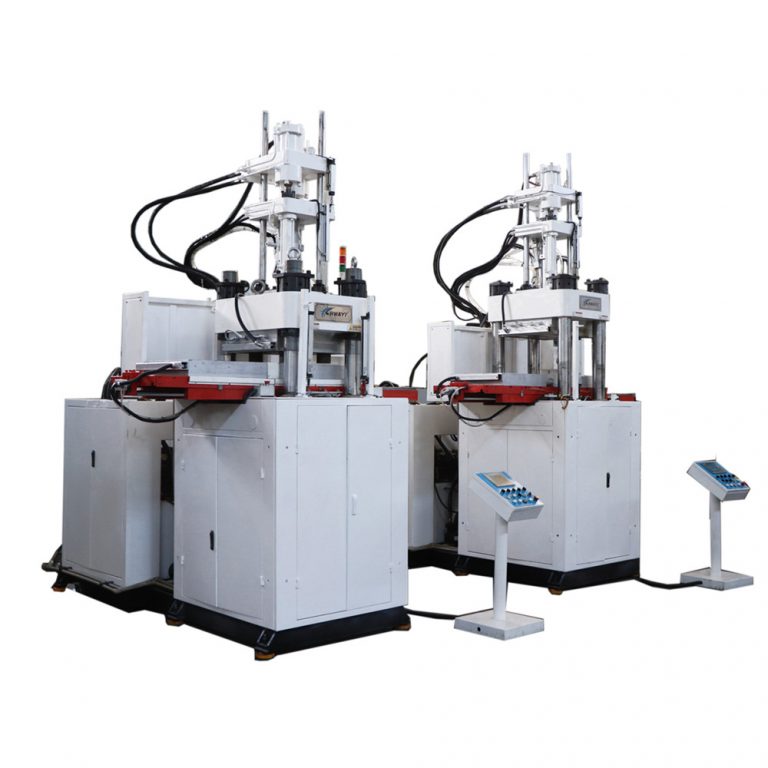
Problem statement: why hydrodynamics and deflection matter on the shop floor
Factory teams chasing higher throughput often push pressurized flow and longer cavities until parts fail to meet tolerances. That trade-off — fluid pressure and structural deflection — is the root cause behind flash, short shots, and premature mold wear on commercial horizontal units. This article lays out clear, mechanics-first steps for diagnosing and controlling those limits, with reference designs for common LSR systems such as the lsr molding machine used across automotive and medical suppliers.
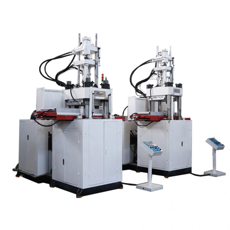
How hydrodynamic forces translate to frame deflection
Injection pressure and melt flow impose distributed loads on the platen, tie bars, and mold base. High pressure plus large shot size creates bending moments that exceed stiffness margins. When the platen or tie bars deflect, clamp force distribution changes, causing uneven cavity filling and variable part dimensions. The practical link: measurable platen parallelism drift after a heavy cycle indicates the system is hitting a hydrodynamic limit rather than a process anomaly.
Common failure modes and diagnostic signals
Failure modes are repeatable and measurable. Track these indicators:
– Flash concentrated at one end of the part: sign of platen tilt and localized seal loss.
– Short shots that improve with slower injection: suggests excessive shear or pressure drop across runners.
– Rapid tool wear near gate areas: indicates high local melt velocity and heat concentration.
– Drift in cavity dimensions across a run: points to thermal growth plus mechanical deflection accumulating over the mold cycle.
Practical mitigation tactics — quick, testable changes
Start with the machine-mold interface, then adjust process variables. These steps are ordered from least to most invasive:
– Verify tie bar preload and platen parallelism using gauges; tighten tolerances before tuning process settings.
– Reduce peak injection pressure and raise injection speed only where needed to maintain fill — this limits pressure-induced bending.
– Shorten melt path length with larger runners or balanced gating to lower pressure drop; this preserves consistent cavity fill and reduces shear. Use the injection unit settings to check pressure curves during the mold cycle.
– If deflection persists, consider stiffening the mold base or adding support pads to redistribute clamp force.
– For LSR and similar materials sensitive to pressure and cure, review cycle cooling and cure scheduling — pressure hold duration affects final dimensions as much as the mold cycle time.
When to upgrade machine hardware
If mitigation tactics fail, the limit is often mechanical: platen stiffness, tie bar diameter, or overall clamp force. Upgrades that yield measurable returns include larger tie bars to reduce bending, higher-rated clamps for more uniform force, and precision platens that maintain parallelism under load. Real-world anchor: automotive suppliers in Detroit shifted to plates with higher moment of inertia after repeated part rejections in high-cavity LSR runs; that change cut rework by a noticeable margin on assembly lines.

Implementation checklist for teams
Use this checklist during root-cause assessment and validation runs:
– Measure pre- and post-run platen parallelism.
– Record pressure and flow curves from the injection unit every shift.
– Log part dimensions across cavities for three consecutive mold cycles.
– Inspect gate and runner wear weekly when running high-velocity recipes.
– Validate changes on pilot runs before scaling to full production — small changes in shot size or clamp force compound quickly.
For teams sourcing equipment, compare models by their rated clamp force deflection and platen stiffness rather than only top-line clamp rating. Consider models optimized for elastomers like an lsr injection machine when working with medical or automotive silicone parts.
Advisory: three golden rules for selecting and setting strategies
1) Match machine stiffness to the largest practical shot size; overspec on platen rigidity rather than dreaming of higher pressure. Measure deflection under a test load and accept only machines that meet a defined mm/ton metric.
2) Control peak pressure, not just average flow. Tune the injection profile so the pressure spike is within the mold’s sealing capability — that prevents localized flash and gate erosion.
3) Verify with real runs and continuous logging. Use pressure and displacement traces over several mold cycles to ensure changes hold under production conditions. Those traces are the single most useful data stream for predicting failures.
Final thought — when the process, the tool, and the machine align, variability drops and throughput actually rises. HWAYI. —