
A Field Test, Not a Brochure
I speak as a grid storage consultant with over 17 years in utility projects. Utility scale battery storage sounds neat on paper; in the field, it’s honest and unforgiving. On February 17, 2021, west of Odessa, I watched a 100 MW / 200 MWh site fight frost, feeder sag, and dispatch swings while the market price jumped by the minute. We had utility scale energy storage systems designed to 2C peak, and the control room still saw response latency spiking above 600 ms during frequency events. That’s not just an annoyance—it’s money gone. So what actually breaks when you need it most?
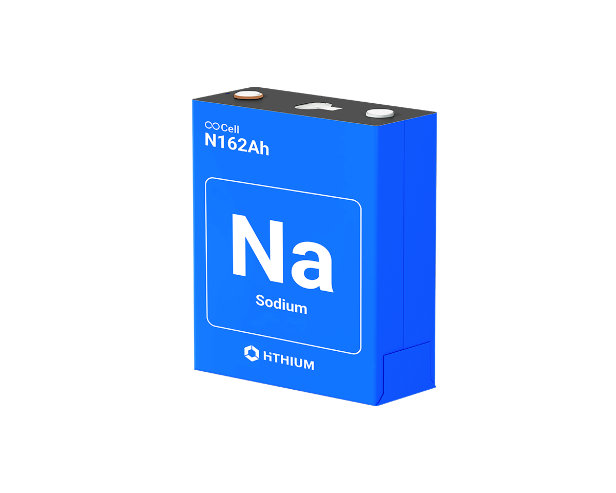
The usual suspects: round‑trip efficiency, thermal limits, and controls stack friction. A power converter derates early when the cabinet runs hot. The BMS throttles because one string hits a high cell delta. SCADA polls too slowly, and the EMS dithers. These are fixable, but not by slogans. No fluff—I’ll keep it plain. When state of charge (SoC) windows, inverter clipping, and battery augmentation collide, projects bleed value in small cuts you only notice on Tuesday’s revenue report. Let’s pull the problem apart.
The Hidden Flaws in Legacy Designs
Where do projects actually lose money?
I’ve walked yards from Blythe, CA to Corpus Christi, TX and seen the same pattern. Legacy designs lean on oversized central PCS units, thin airflow, and a slow control loop. In July 2019 near Blythe, a 50 MW block with NEMA 3R cabinets hit internal 44°C by noon; the PCS derated by 8% and the DC bus ripple worsened under ramping. The BMS shifted to conservative limits, squeezing usable kWh by roughly 6%. On paper, availability looked fine. In practice, you lost a slice of every 5‑minute interval. Frequency regulation wants sub‑second response; SCADA polling at 2 seconds is a penalty baked into the day.
Then there’s augmentation. Too many projects bolt on extra MWh with mismatched impedance a year or two in. Mixed‑vintage racks force the BMS to protect the weakest strings, especially when SoH diverges. Result: the “new” MWh show up in reports but not in dispatch. I’ve measured 92% round‑trip efficiency on mixed packs that should have done 95%—those three points cut annual margin by six figures on a 100 MW site. And I still see thermal systems that rely on passive airflow instead of liquid cooling, which can keep LFP cells in a 25–30°C band with far tighter delta‑T across modules. When the cells stay even, balancing currents drop and cycle life rises. Simple physics—yet ignored because the datasheet looked pretty.
Controls come last in many budgets, and that’s a miss. If your EMS resolves setpoints every 1–2 seconds and your inverter firmware applies them with a 300–500 ms lag, you can’t catch fast ramps. Add interconnection headroom rules and the PCS will clip to stay safe, even when the bus could handle a 1.2 p.u. surge for a short duration. In ERCOT, I’ve seen 20–30% of a peak hour get curtailed this way. It isn’t dramatic, but it’s relentless. And yes—those little events are why the monthly settlement doesn’t match the banker’s model.
What’s Next, And What Actually Wins
Real‑world impact
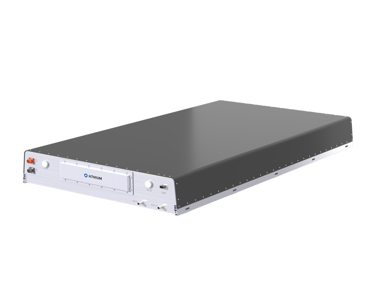
We’re moving from monolithic stacks to modular, fail‑in‑place designs. String‑level power converters with soft‑switching topologies reduce switching losses and heat, which lifts effective round‑trip efficiency by 1–2 points in real markets. Pair that with liquid cooling loops and active balancing (3–5 A per string), and your SoC spread shrinks under heavy cycling. Edge computing nodes at the container level now run fast dispatch logic locally—no need to wait on a slow SCADA round trip. The result is what operators actually want: 250–400 ms net response to a change in setpoint, even when ambient is ugly. I prefer this architecture because it survives faults without tripping the whole block. One string misbehaves, the rest keep earning—clean and quiet.
Case in point: a 150 MW / 300 MWh LFP site in Andrews County commissioned in Q3 2023. We tuned the EMS to 200 ms control intervals, set inverter limits with short‑duration headroom (with protection, not bravado), and kept cell temps under 30°C even at 1C. Effective forced outage rate fell from 8% during provisional tests to 1.5% by month three. Ancillary revenue rose about 11% quarter‑over‑quarter simply by hitting the ramp windows consistently. That didn’t come from magic—it came from small design choices that stacked. These are the same principles behind modern utility scale energy storage systems: tighter thermal control, faster control loops, and modular power paths that don’t cascade into outages.
Comparisons help. LFP cells at 314 Ah with liquid cooling maintain capacity under 35°C cycling far better than air‑cooled racks with mixed vintages—by year two, I typically see 1–1.5% less degradation per equivalent full cycle. A system with local edge logic and 100 ms telemetry can ride through feeder flicker without jogging between states; older SCADA‑only stacks stumble and then overcorrect. And when we modeled LCOS last December in a CAISO case, that 3% efficiency gap roughly equaled $2.70/MWh—quiet, persistent, decisive. I’ve learned to chase the boring numbers; they pay the bills. — and they’re measurable.
If you’re choosing a platform, anchor on three checks I use in the field: 1) sub‑second closed‑loop response under a 50% SoC step (prove it with recorder traces, not sales slides), 2) thermal stability that keeps cell delta‑T under 3°C at 1C charge in 35°C ambient, and 3) an augmentation plan that maintains impedance parity across racks, documented by weekly SoH spread. Meet those, and the rest—warranty claims, O&M hours, even firefighter sign‑off—gets simpler. For a clear look at the solutions tier that implements these principles, see HiTHIUM.