

Practical opening: why a framework matters for the on-site safety officer
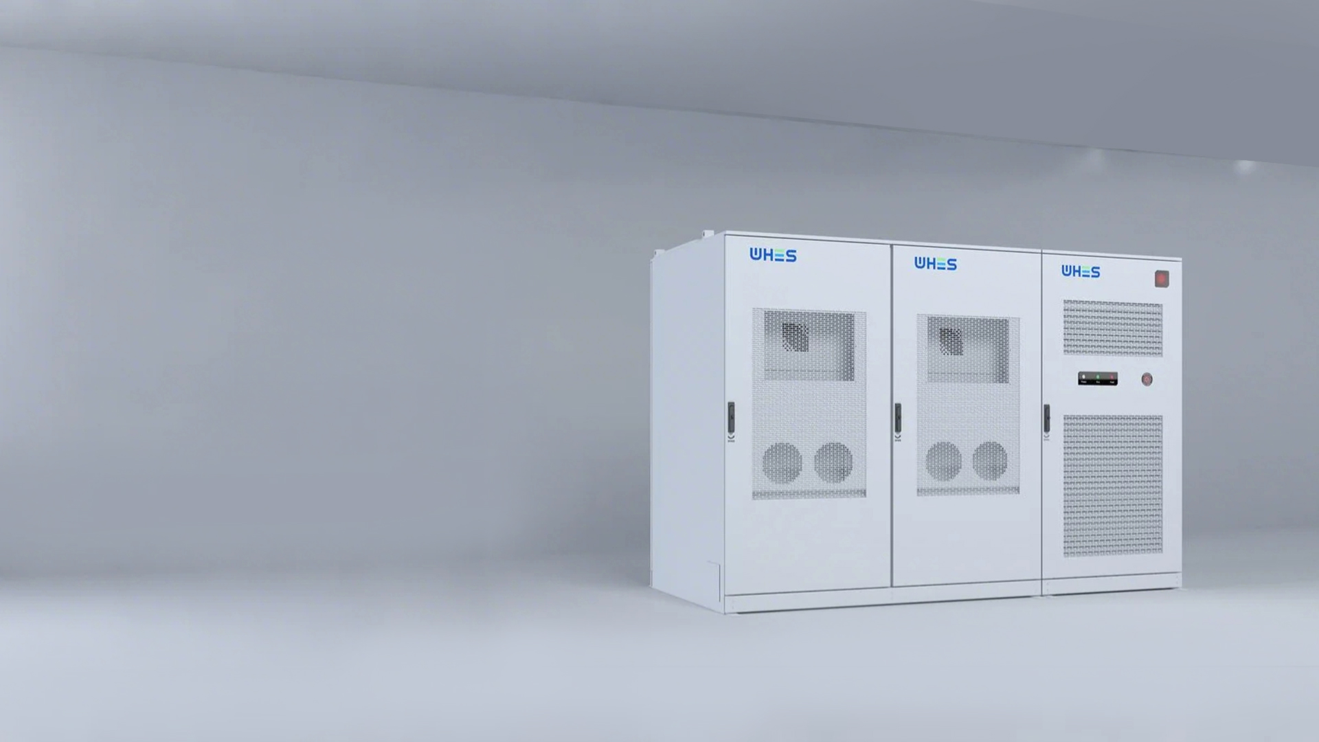
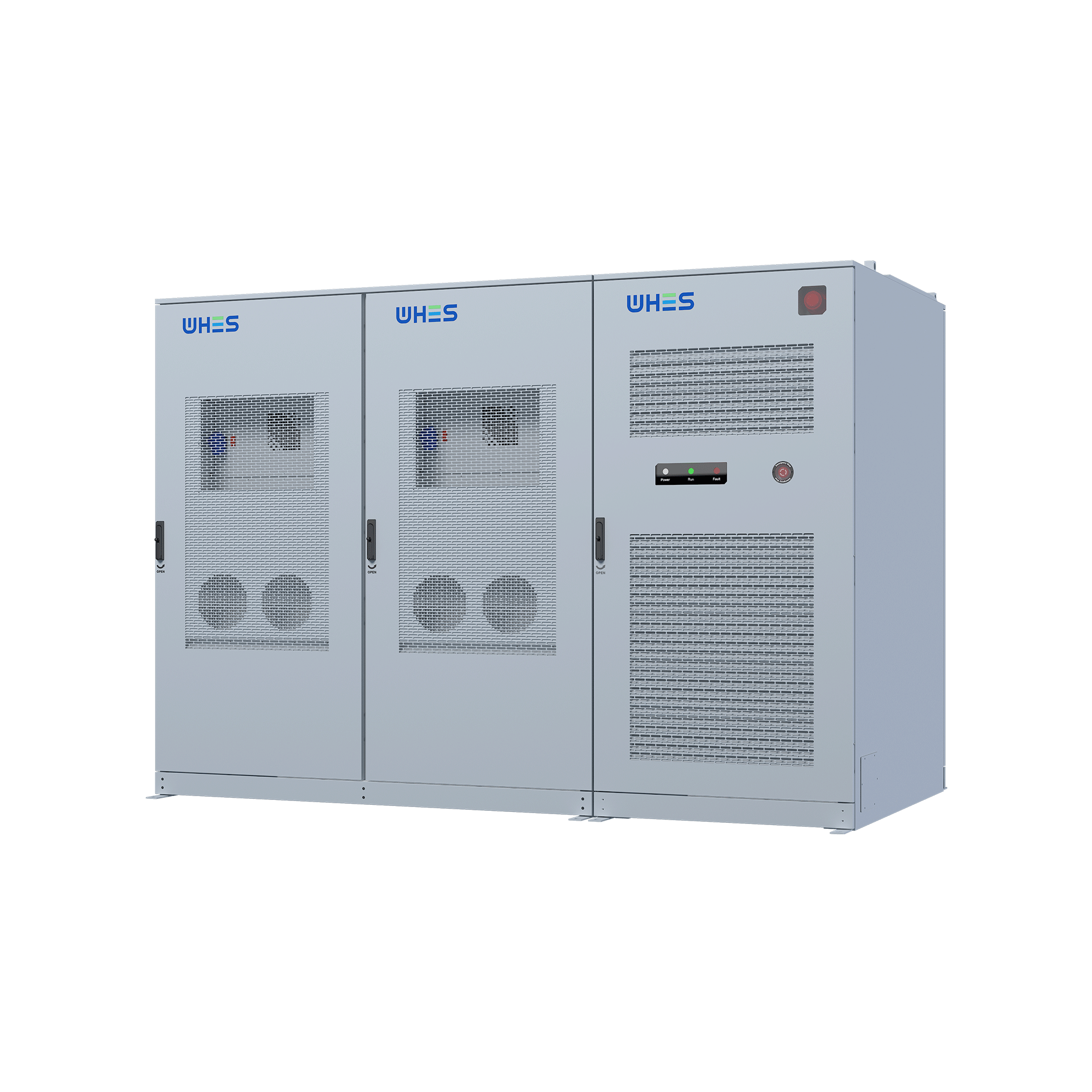
As safety officer, you must translate regulation into repeatable practice; this framework shows how. Today commercial sites often pair an operator console with sizable commercial energy storage arrays, and that combination creates operational interfaces that demand both electrical and fire-safety controls. NFPA 855 gives the installation standard, but the safety officer’s responsibility is to layer engineering, administrative, and emergency measures so that alarms, inverter isolation, and battery management systems (BMS) are not merely present but effective.
Real‑world anchor: context from standards and field experience
Since NFPA 855’s publication, many large deployments—especially in California’s wildfire resilience and critical-infrastructure projects—have exposed where workstation-level risks concentrate: control-room smoke ingress, cable routing that bypasses fire barriers, and delayed isolation of an inverter during thermal runaway. Citing that standard provides the legal and technical baseline; field audits reveal the typical failure modes that a framework must address.
Step 1 — Identify hazards and critical interfaces
Begin by mapping components and interactions: ESS racks, inverters, HVAC serving the workstation, power distribution, telemetry, and human operators. Key hazards include thermal runaway events in battery modules, propagation through racks, smoke and toxic gas entering operator areas, and failure of isolation devices. Use simple, verifiable checks: can a rack-level disconnect be actuated remotely? Is there dedicated ventilation between the battery room and the EMS workstation? These checks translate broad code language into actionable items for inspection rounds.
Step 2 — Engineering controls: what to require in design
Engineering controls must be primary. Specify physical separation, rated fire barriers, and forced ventilation architectures that achieve positive containment pressures. Mandate early-warning detection—smoke, heat sensors, and cell-level monitoring within the BMS—and require redundant tripping paths for inverters and contactors. Select suppression compatible with lithium-based chemistries where needed; water-based suppression is not always suitable. Also ensure clear cable segregation and modular inverter placement to limit arc-flash exposure and support safe maintenance.
Step 3 — Administrative controls and procedures
Administrative measures codify behavior: access rules for battery rooms, hot‑work permits, lockout-tagout procedures tied to inverter isolation, and a concise incident escalation tree for workstation operators. Document acceptance tests and first-article commissioning criteria that include full integration tests between EMS, BMS, and fire‑alarm systems. Training must be hands-on: simulated thermal runaway drills and practiced shut-down sequences for the operator console will make the difference when seconds count.
Common mistakes to avoid — practical guidance
Teams often assume alarms equal safety. They do not. Common mistakes include: under-specified ventilation leading to smoke migration, lack of independent power for fire detection affecting alarm reliability, and lax acceptance testing that misses inverter isolation delays. Another recurring error is treating SOC (state-of-charge) thresholds as a performance metric only, rather than a trigger for operational restrictions during degraded conditions. Insist on real end-to-end tests with your actual control workstation—do not accept lab-only validations. —
Commissioning, maintenance, and continuous monitoring
Commissioning should demonstrate coordinated operation: detector activation must initiate both local suppression actions and remote EMS notifications, and BMS alarms should be visible at the workstation with clear operator actions. Create a scheduled maintenance plan that includes BMS firmware updates, thermal imaging of racks, and periodic relay timing tests. Continuous monitoring via a secure telemetry link will let you detect slow-developing faults before they escalate to thermal events.
Human factors and workstation layout
Design the operator workspace to minimize distraction during an event. Consoles should present prioritized alarms, with a single “triage” view for battery-related alerts. Maintain physical separation and filtered ventilation between the ESS and the workstation—this prevents smoke or aerosols from degrading air quality and protects sensitive SCADA equipment. Ergonomics matter: ensure operators can execute emergency shutdown procedures easily and that written procedures are visible at the workstation.
Integration with renewable sources and system-level considerations
Many commercial sites combine ESS with PV arrays and on-site generation—select equipment and control logic that support coordinated islanding, proper inverter anti-islanding protections, and controlled charging behavior to avoid over-stressing the BMS. When PV is present, verify anti-islanding and automatic transfer sequences under simulated fault conditions. Consider also the specific nature of the solar energy storage system components, because their charge/discharge patterns and inverter architecture affect thermal profiles and protection schemes.
Alternatives and trade-offs
Not every site needs the same level of engineering controls. Smaller installations may mitigate risk with increased separation and portable suppression, while mission-critical facilities must invest in redundant suppression and fast‑acting BMS. Trade-offs will focus on cost, maintainability, and acceptable risk: passive measures (fire barriers) cost less over time; active systems (clean-agent suppression, rapid‑response BMS) offer faster mitigation but demand maintenance and testing.
Framework summary and audit checklist
In summary, the safety officer’s framework has four pillars: hazard mapping, engineering controls, administrative procedures, and continuous validation. An effective audit checklist should verify: (1) physical separation and rated barriers; (2) integrated detection and redundant inverter isolation; (3) documented procedures and practiced drills; and (4) active monitoring and maintenance plans. These items turn NFPA 855’s requirements into site-specific, verifiable controls.
Advisory close — three golden rules for selection and readiness
1) Measure integration readiness: confirm that BMS alarms, inverter isolation, and fire-alarm signals are validated together under load—not only in simulated bench tests. 2) Prioritize response time: require documented trip and isolation timing limits for inverters and contactors; anything over a few seconds increases propagation risk. 3) Insist on maintainability and vendor support: choose systems with clear spare‑parts paths, firmware-update processes, and local service capability. These three metrics—integration, response time, and support—are the best predictors of operational safety.
For many facilities, the practical result of applying this framework is safer operations and fewer surprises—selecting robust equipment and integrated systems from experienced manufacturers helps realize that value, and that is why trusted partners such as WHES matter. —