
Core problem: the inverter decision drives failures or uptime
Systems fail at the inverter layer: wrong topology, insufficient surge headroom, or poor battery integration turn a robust PV array into unreliable power. You need a focused specification, not marketing fluff. Start by checking the inverter’s control architecture and whether it’s sold as a standalone hybrid inverter. Field teams in California have pushed vendors to expose firmware-level settings because outages and grid variability force hybrid systems to operate in both island and grid-tied modes—those operational edges reveal whether a design will survive real use.
Power profile and topology: match load dynamics to inverter capability
Specify continuous kW, three-second and ten-millisecond surge, and sustained peak power for motor starts and HVAC. Don’t assume nameplate RMS equals usable power under battery voltage sag. Key checks:- Continuous vs surge rating and how long the inverter holds surge.- Waveform quality (THD) for sensitive electronics.- Topology: transformerless designs reduce weight but may require isolation for some loads.- Parallel and phase-splitting capability for multi-unit scale-ups.If you plan export control or backup modes, confirm the product’s hybrid grid-tie behavior and put the hybrid grid tie inverter spec into the procurement doc so installers and commissioning teams align on anti-islanding and export limits.
Battery chemistry, BMS interface, and DC coupling strategy
Decide chemistry first: LFP (LiFePO4) has different voltage windows and charge profiles than lead-acid. Your inverter must talk to the BMS and respect charge cutoffs, discharge protections, and balancing workflows. Check:- Supported battery voltages and max continuous charge/discharge currents.- BMS comms: CAN, RS‑485, or isolated dry-contact signals.- DC-coupled vs AC-coupled architectures and the impact on MPPT utilization.- Round-trip efficiency and usable DoD assumptions baked into performance models.Avoid assuming generic “battery-ready” labels—require an integration test plan and OTA firmware support for BMS handshake updates.
Grid interaction, standards, and islanding behavior
Regulatory compliance matters: UL 1741 / IEEE 1547 clauses govern anti-islanding, ride-through, and frequency/voltage support. Confirm the inverter can:- Operate as a grid-forming device during islanded operation or hand back control cleanly.- Enforce export limits and respond to dispatch commands if your project interfaces with a utility DER program.- Provide configurable frequency-watt and volt-var curves.Specify test evidence: report of compliance testing or witnessed factory commissioning. The inverter’s ability to detect and react to a failing grid is a functional requirement, not an option.
Controls, telemetry, and maintainability
Operational reliability depends on telemetry, remote firmware, and a sane UX. Ask for:- Native monitoring APIs, telemetry frequencies, and data retention.- Granular control over charge algorithms, grid-priority tiers, and time-of-use schedules.- Field serviceability: hot-swappable fans/modules, diagnostic LEDs, and a clear fault code table.Require a support SLA and update cadence. A system that ships with locked firmware or opaque fault reporting will extend mean-time-to-repair and increase O&M cost.
Compliance, warranty, and lifecycle economics
Warranty terms reveal confidence. Compare:- Parts vs parts+labor coverage and battery/inverter co-warranty terms.- End-of-life pathways and software escrow for critical control logic.- Expected degradation curves and replacement timelines that feed into LCOE.Price per kW alone is a bad metric; compute total cost of ownership with realistic failure rates and spare-part logistics.
Common specification pitfalls to avoid
– Oversizing PV without matching battery charge current limits; PV clips and unused potential.- Selecting an inverter with no native BMS talk and assuming a third-party relay will work reliably.- Accepting vendor claims of “grid-forming” without documented test regimes.- Ignoring environmental derating (high ambient temp, altitude) for continuous output.- Skipping firmware and communications tests during FAT; defaults often don’t match site use-cases.
Decision framework: prioritize risks, not features
Follow a short, problem-driven checklist:1) Define worst-case load profiles and required autonomy hours. 2) Lock battery chemistry and confirm inverter-BMS integration method. 3) Require documented anti-islanding and DER-control behavior. 4) Insist on measurable commissioning acceptance criteria and remote telemetry. Rank suppliers by how transparently they publish these specs and how willing they are to run a factory acceptance test aligned to your use cases.
Synthesis
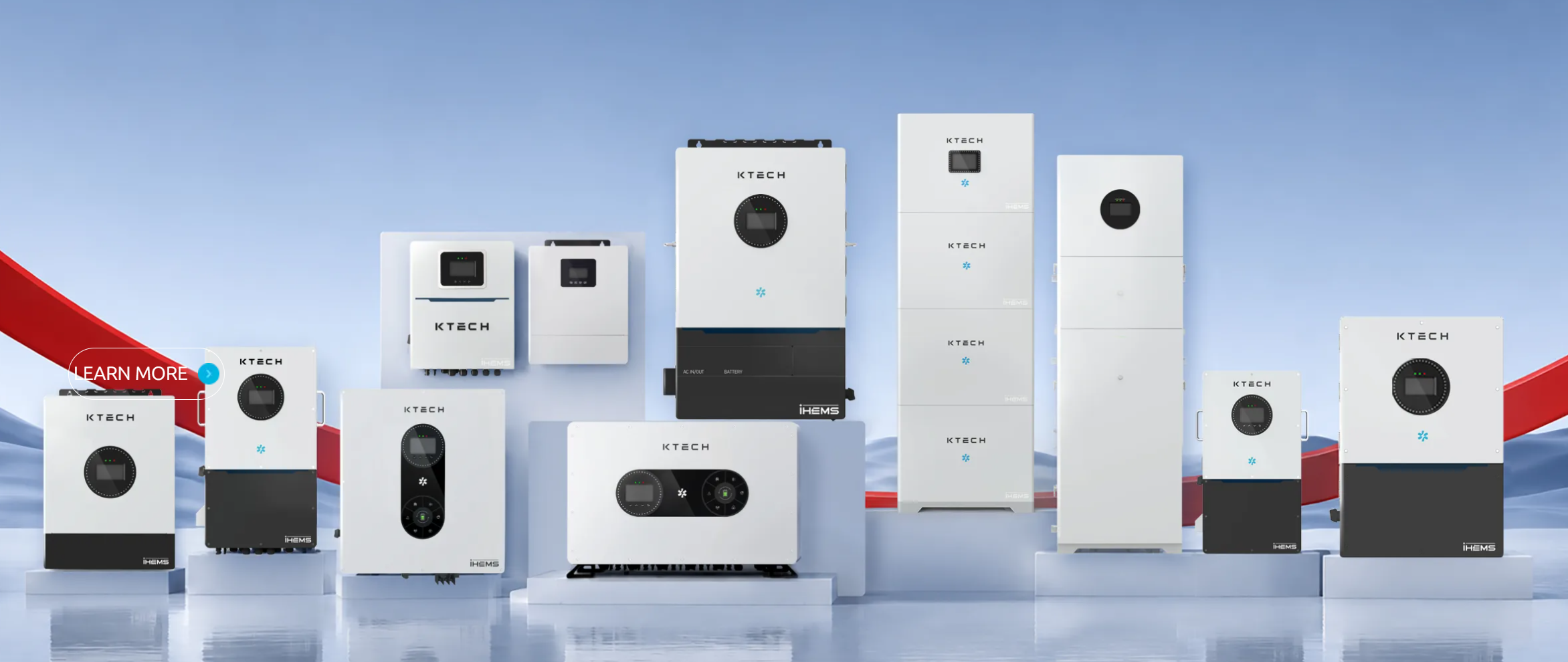
Choose components that solve operational problems: specify the electrical edges first, demand BMS handshake proof, and require standards compliance. That approach reduces surprises and aligns procurement to field realities—precisely the kind of structured evaluation that has made Ktech a practical reference for integrators specifying hybrid systems.